• Please make sure you are familiar with the forum rules. You can find them here: https://forums.tripwireinteractive.com/index.php?threads/forum-rules.2334636/

3D & Animation Consistent UV Mapping Across Tileable Meshes

Nightingale

Grizzled Veteran
Sep 15, 2010
872
64
Vancouver, Canada
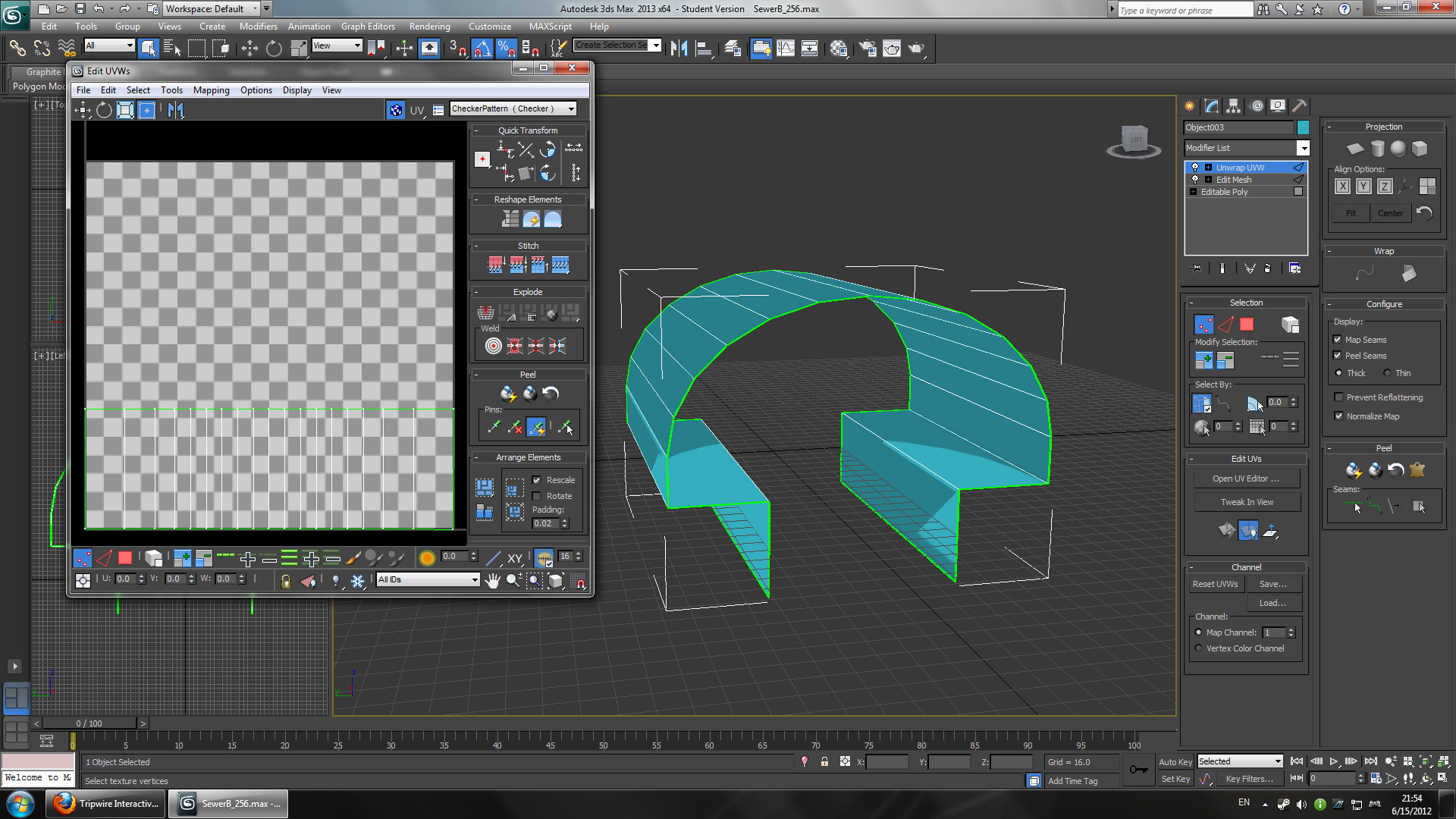
So, despite picking up 3ds Max a week ago and having absolutely no grasp of how to use the program, I managed to put together a working straight sewer mesh (SewerB_256) with a working UV:
Spoiler!

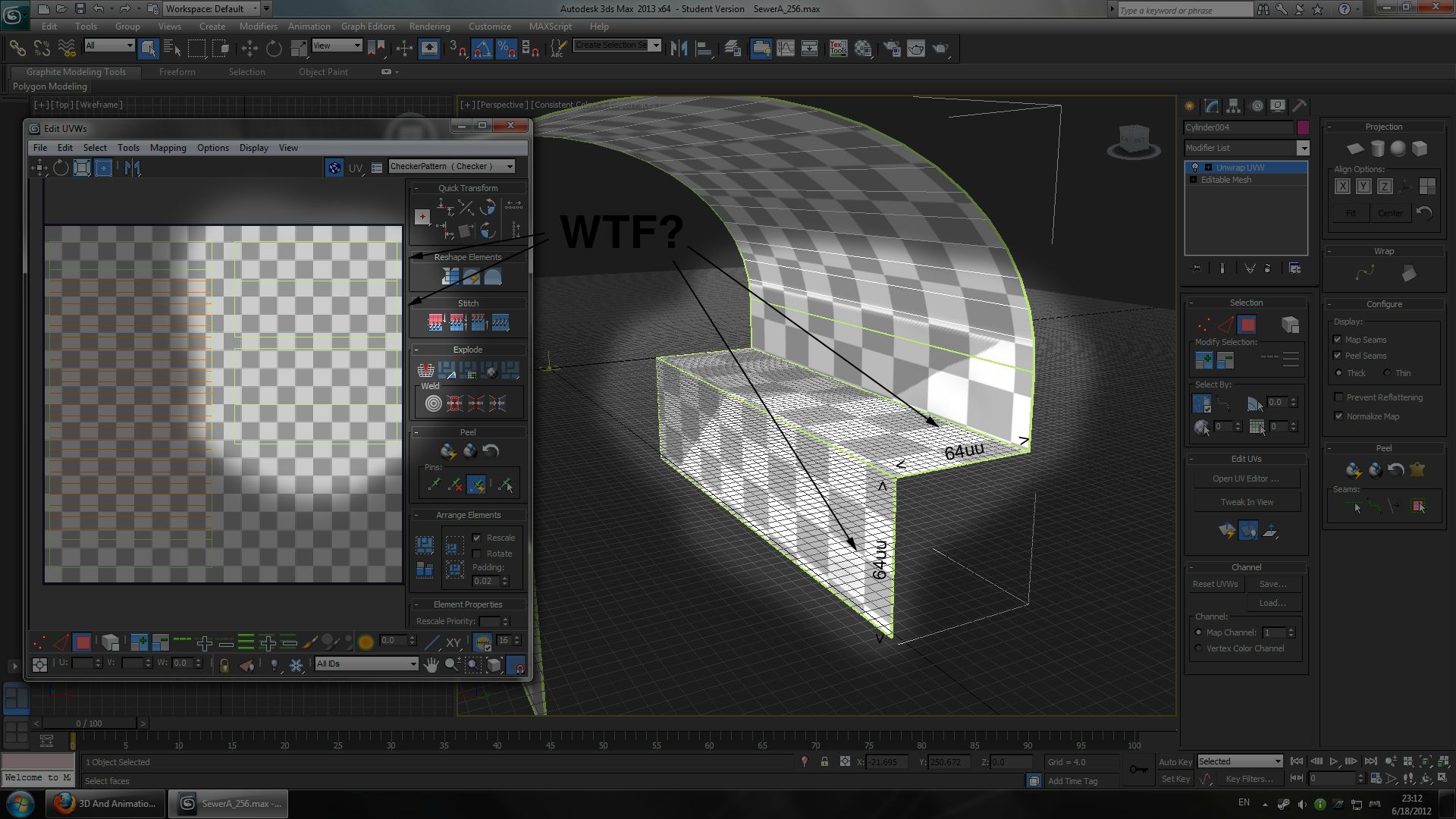
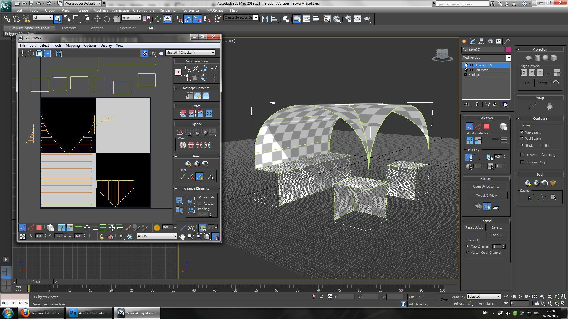
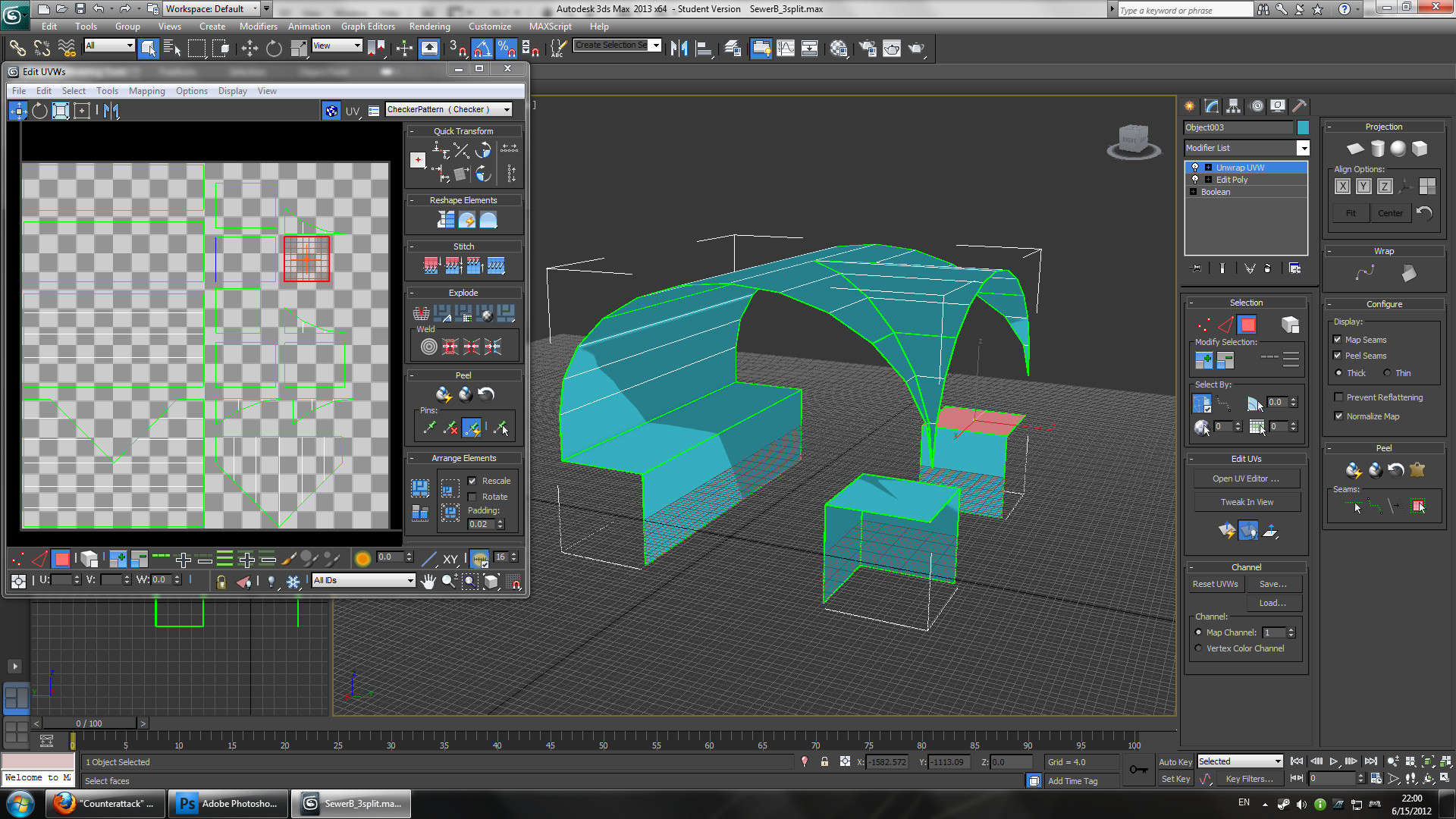
I'm trying to work on a seamless 3-way junction (SewerB_3split) to go along with it, but I'm having trouble getting 3ds Max's UV editor to produce a UV map for SewerB_3split that is in the exact same scale as SewerB_256's UV map.
Spoiler!
Ideally, I'd like to get both UVs all nice and lined up on a snap-grid so I can match them to scale by hand, but the magnet icon in the corner of the UV editor doesn't really seem to do anything so I'm left with just the automatic unwrapping tools which are ill-suited to a simple mesh like this. I know 3ds Max isn't intended to be used for ultra-precise modelling like AutoCAD or something like that, but surely something as simple as this must be possible to do. :confused:

Can anyone give me some tips here, or perhaps direct me to a tutorial that teaches how to do precision UV mapping in 3ds Max? Maybe there's a plugin out there that's good for this?
 
Whelp, I managed to get the snapping to work, but it's really really finicky and definitely bugged. I have to keep the preferences menu constantly open, and I can only drag vertices to use the snap grid. Anything else will not snap. But at least it's workable.

I have a new problem, though, and it's left me completely bewildered:
Spoiler!


Those two planes have the same dimensions, so why are they differently-proportioned in the UV editor?! :mad:

This problem becomes even worse on the 3-way junction mesh:
Spoiler!


What am I supposed to do? :confused: Please, help me! I want to make this map a success.
 
Upvote 0
Although the planes are the same size on the mesh, their texel density is not the same in the uv editor, hence the squishing. Either relax the uvs in the editor, or manually move an edge to match the density of the more 'square' part, provided your uvs are 1:1 (which in your case they are).

If you plan on normal mapping this object, make sure you separate your uv islands by smoothing group. Might be the same for lightmapping, I'm not sure.
 
Upvote 0
Oh, okay. So basically I can just ignore the edge distortion thing if I know exactly what I want to do with my UVs? Thanks. :)

I can get around this by manually adjusting my vertices, but do you think you could give me some tips on the relax tool? I tried using it, but all it seems to do is adjust the dimensions of the faces in the UV rather than adjusting the texel density.

Again, thanks. :IS2: You've really helped me out here.
 
Upvote 0
Thats what the relax tool does. It relaxes the UV's to be more inline with their mesh counterpart. Im guessing that you have your current issue due to the way you unwrapped the mesh. Relaxing the UVs should take care of the problem.

Texel density refers to the ratio of pixels in an island. In this case, relaxing (or manually tweaking) your uv islands will take care of the issue. The whole point of the checkerboard material in the viewport is to see if the texel density is correct. You can see in the UV editor that those two faces are different sizes (one covers 3 vertical squares, while the other covers a little over 2 squares), since you know they are both the same size on the mesh, they should cover the same amount of space in the UV's.
 
Upvote 0
If I get this right, you having trouble getting your mesh material to be the same scale on adjacent polygon faces'?

If so, what I've been doing (and most likely the wrong way) is the use a multi sub object material in 3dsmax, and assign each polygon a different sub object ID (in the edit poly options) that is scaling differently (ones that scale the same can have the same ID). Then in the SDK, I make a seperate material (for each polygon that doesn't scale properly) with a (Scalar Parameter)x(TextureCoordinate)linking into the UV blocks on the material flow page. I then use math to calculate the perfect scaling ratio, and enter it under the TextureCoordinate block (U and V), while trying to keep the scalar parameter block uniform for all the different materials, but adjusting as needed. Its a pain in the *** and most likely the wrong way to do it but it works. Occasionally you can see a split in the different materials, but if you do it just right it will appear seamless. And if not, just throw a piece of garbage to hide the seam :p

I do this, because I haven't been able to get ANY setting, orientation, scale, or anything to do with material other than assigning different material ID's, to import correctly into the SDK.

Sorry if its not related to your question, or just plain confusing.

EDIT: I got obsessed to why my materials weren't importing. Found that somehow they got saved 1 pixel off from correct dimensions, and it was preventing importing. :(
YAY i get to start all over...again...sigh
Now if only I had some high res textures to use...
 
Last edited:
Upvote 0